MicoAir-WiFi-Link Dual-Band WiFi 6 Telemetry Module
Powered by OFDMA and downlink MU-MIMO technologies, ensuring more reliable wireless connections for multi-drone networks.


Overview
Typical Applications
- Open-source Flight Controller (ArduPilot/PX4) Wireless Tunining: Supports Ground Control Station (GCS) software such as Mission Planner, QGroundControl (QGC), and MicoPilot.
- Drone Swarm Light Show Networking: Enables multi-drone swarm communication, waypoint data, and command upload (supports Skybrush).
- Robotics and Unmanned Systems Wireless Access: Suitable for various control and debugging scenarios requiring short-range, high-bandwidth wireless communication.
Product Features
- Powered by ESP32-C5
- Dual-band WiFi: 2.4 GHz / 5 GHz
- Supports WiFi 6 (802.11ax), backward compatible with 802.11 a/b/g/n/ac
- Defaults to AP mode for direct connection
- Supports STA mode for connecting to a router
- Supports bidirectional Serial <-> UDP transparent transmission
- BLE serial transparent transmission (Bluetooth connection currently only supported by MicoPilot)
- Built-in web-based configuration page
- Parameter configuration via USB serial AT commands
- Firmware upgrade via MicoAssistant
Parameters
- Main Controller: ESP32-C5
- Wireless Standard: WiFi 6 / 802.11ax, backward compatible with 802.11 a/b/g/n/ac
- Frequency: 2.4 GHz / 5 GHz
- Communication Interface: LVTTL (3.3V) Serial / USB-Type-C (CH340)
- Core Functions: WiFi UDP Serial Transparent Transmission / BLE Serial Transparent Transmission (BLE currently only supported by MicoPilot)
- Default WiFi Mode: AP (Can be switched to STA mode via AT commands)
- Max Range (AP Mode): 100 meters (Direct connection to phone/PC, tested in open environments without interference)
- Max Range (STA Mode): 500 meters (Relayed via high-power router, tested in open environments without interference)
- Max Range (BLE): 10 meters
- Operating Voltage: 5V
- Avg. Operating Current: 150mA
Serial Port
- Debug Port Baud Rate: 115200
- Telemetry Port Baud Rate: 57600 / 115200 (Default) / 230400 / 460800 / 921600
Default Network Parameters
- AP SSID: MicoAir_WiFi_Link_XXXX
- AP Password: 12345678
- AP Gateway: 192.168.4.1
- STA Local IP: 192.168.1.101
- STA Target IP: 192.168.1.2
- STA Gateway: 192.168.1.1
- UDP Port: 14550
WiFi Operating Modes
- AP Mode (Default): The module creates its own WiFi hotspot. The Ground Control Station (PC/Phone) connects directly to it.

- STA Mode: The module connects to an existing local router. The GCS and the module communicate within the same Local Area Network (LAN).

BLE
- Bluetooth Name: MicoAir_BLE_XXXX
- Bluetooth Password: None
- Connection Range: 10 meters
- Conflict with 2.4G WiFi: Since BLE and 2.4G WiFi share the same physical antenna and channel, they cannot be used simultaneously. The factory default is 5G WiFi (AP Mode) + BLE. If the module is switched to 2.4G WiFi (AP Mode), BLE will be automatically disabled. In STA mode, connecting to a 2.4G router will also automatically disable BLE.
Interface Description
Telemetry Interface
- TX and RX must be cross-connected.
- The flight controller and the module must share a common ground (GND).
- The flight controller serial baud rate must match the module’s configured baud rate.

Debug Interface
- Configuring parameters via AT commands.
- Firmware upgrades.
Web Configuration Guide

Physical
- Dimensions: 34.5×23.5x6mm
- Weight: 5.5g (without antenna)
AT Command List
| Command | Description |
|---|---|
AT | Test communication, returns OK |
AT+ALL? | Query all current configuration information |
AT+STATUS? | Query the current network state and core parameter configuration |
AT+MODE? / AT+MODE=<0/1> | Query / Set operating mode (0: AP Mode, 1: STA Mode) |
AT+BLE? / AT+BLE=<0/1> | Query / Set BLE telemetry switch (0: Disabled, 1: Enabled) |
| Query / Set WiFi channel (Only effective in AP mode) |
AT+APSSID? / AT+APSSID=<ssid> | Query / Set the module’s AP hotspot name (Max 32 characters) |
AT+APPWD? / AT+APPWD=<pwd> | Query / Set the AP hotspot password (8~63 characters) |
AT+SSID? / AT+SSID=<ssid> | Query / Set the target router SSID (Used in STA mode) |
AT+PWD? / AT+PWD=<pwd> | Query / Set the target router password (Used in STA mode) |
AT+BAUD? / AT+BAUD=<baud> | Query / Set the telemetry serial port baud rate communicating with the flight controller |
AT+PORT? / AT+PORT=<port> | Query / Set the UDP communication port (Default 14550) |
AT+MIP? / AT+MIP=<ip> | Query / Set the module’s Local IP (Static IP) |
AT+GW? / AT+GW=<ip> | Query / Set the Gateway IP (Used when setting a static IP in STA mode) |
AT+TIP? / AT+TIP=<ip> | Query / Set the target communication IP |
AT+VER? | Query firmware version information |
AT+RST | Reboot the module (Requires execution after modifying parameters to take effect) |
AT+RESET | Restore factory default settings |
AT Command Usage Examples
Below are typical operation steps for common scenarios. The module generally replies with OK after successfully executing a command.
Example 1: Query current module state and parameters
Confirm the current network status and parameter configuration.
Send: AT+STATUS?
Similar response:
Mode: AP
AP_SSID: MicoAir_WiFi_Link_ABCD
AP_PWD: 12345678
IP: 192.168.4.1
Baud: 115200
UDP_Port: 14550
Target_IP: 255.255.255.255
OK
Example 2: Modify the telemetry serial baud rate
When a higher baud rate is required for the connection between the flight controller and the module (e.g., changing to 460800):
Send: AT+BAUD=460800
Response: OK

Send: AT+RST
Response: OK
(The new baud rate takes effect after reboot. Future AT command communication and flight controller connection must use the new baud rate.)
Example 3: Switch to STA mode and connect to a router
To increase communication range or to allow multiple devices to join the same LAN, set the module as a client (STA Mode) to connect to an existing wireless router (e.g., target router SSID MyRouter, Password password123).
1. Set the target router SSID Send: AT+SSID=MyRouter Response: OK 2. Set the target router password Send: AT+PWD=password123 Response: OK 3.Set a static IP. : Send: AT+MIP=192.168.1.101 Response: OK4.Set the Target(PC) IP. :
Send: AT+TIP=192.168.1.200 (Your PC IP)
Response: OK
5.Set the operating mode to STA Mode (Mode ID: 1)
Send: AT+MODE=1
Response: OK
Example 4: Modify the default AP password
In the factory default AP mode, modify the AP password to enhance privacy and prevent unauthorized access (minimum 8 characters required):
Send: AT+APPWD=my_new_pwd
Response: OK

Send: AT+RST
Response: OK
(After reboot, clients connecting to the module's hotspot will need to input the new password.)
Ensure that the telemetry module is correctly connected to the flight controller’s serial port, and the corresponding FC serial port baud rate is set to 115200 (MicoAir-WiFi-Link default baud rate).
MicoPilot Connection Tutorial
BLE Connection Instructions: First, ensure your smartphone’s Bluetooth is enabled. Open the MicoPilot Ground Control Station APP, tap the
Connectbutton in the top right corner, and select Bluetooth mode. A Bluetooth connection window will pop up and automatically display discovered Bluetooth devices. Wait a few seconds, and you should see the MicoAir-WiFi-Link device name (e.g., MicoAir_BLE_XXXX) in the first row, as shown below. Tap to connect.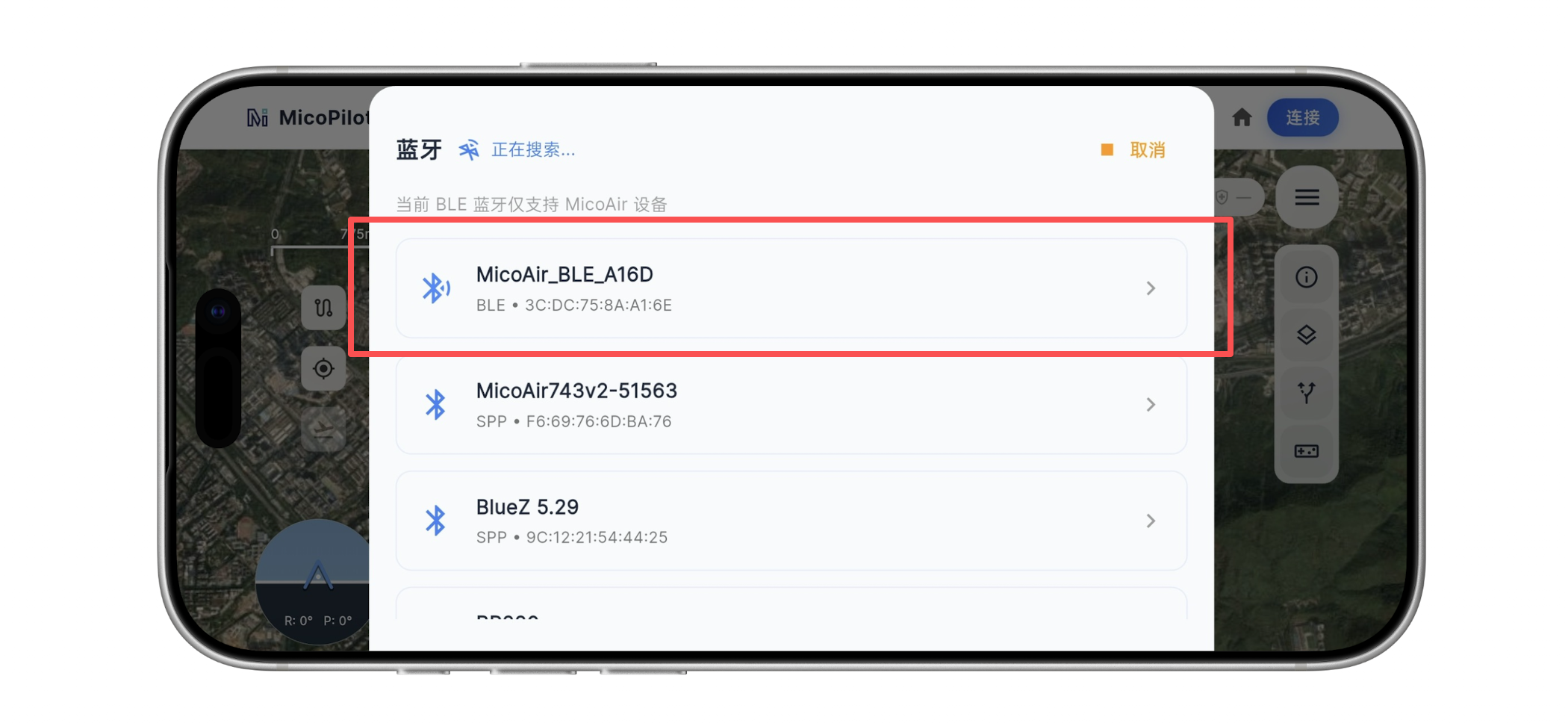
WiFi UDP Connection Instructions:
First, connect your smartphone to the module’s WiFi hotspot, typically named: MicoAir_WiFi_Link_XXXX. Open the MicoPilot APP, tap theConnectbutton in the top right corner, and select WiFi/UDP. A UDP connection window will pop up—select UDPCI mode, leave the gateway IP and port at their default values (192.168.4.1 and 14550), and tap Connect.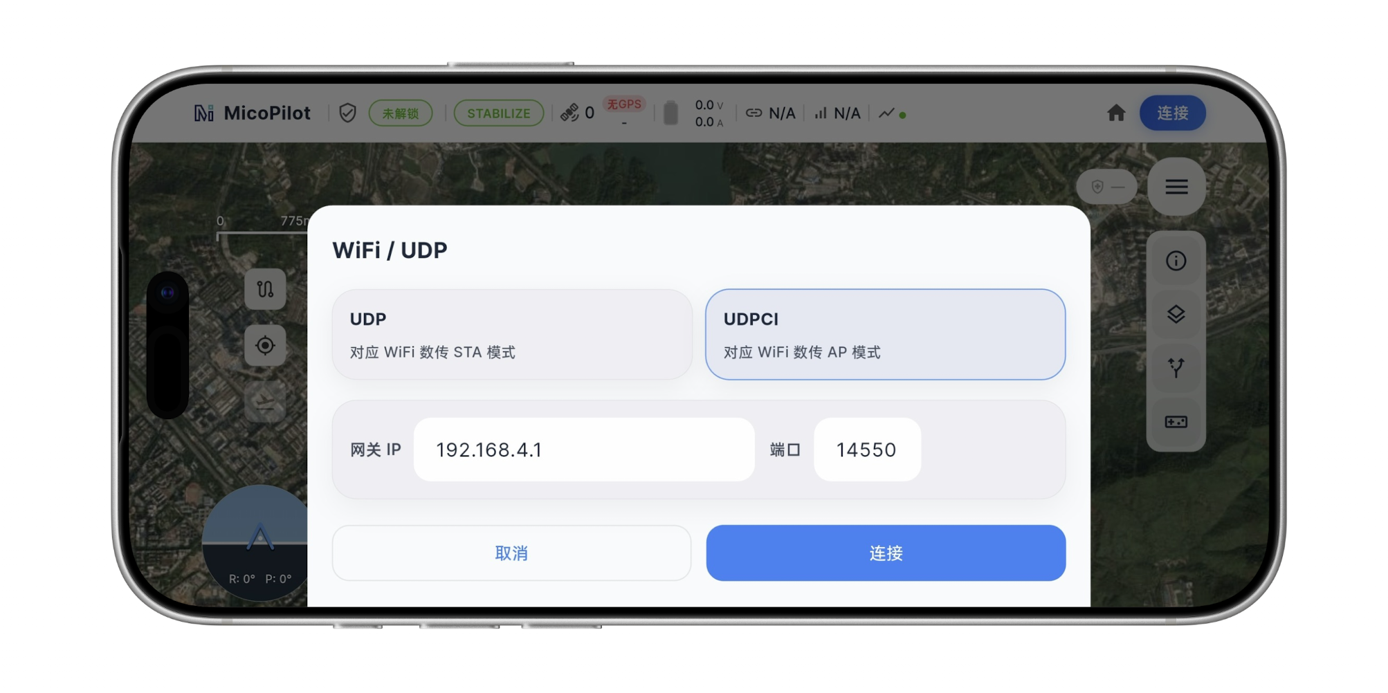
Mission Planner Connection Tutorial (AP Mode)
In the top right corner of Mission Planner, select UDPCI mode, and click Connect. In the popup dialog, enter the telemetry module’s gateway IP address: 192.168.4.1, and port number 14550. MP will automatically begin connecting to the flight controller. If it takes too long or fails to retrieve flight controller parameters, please verify whether your PC is connected to the WiFi hotspot, the FC serial baud rate is properly set to 115200, and the wiring is correct (Rx and Tx must be cross-connected).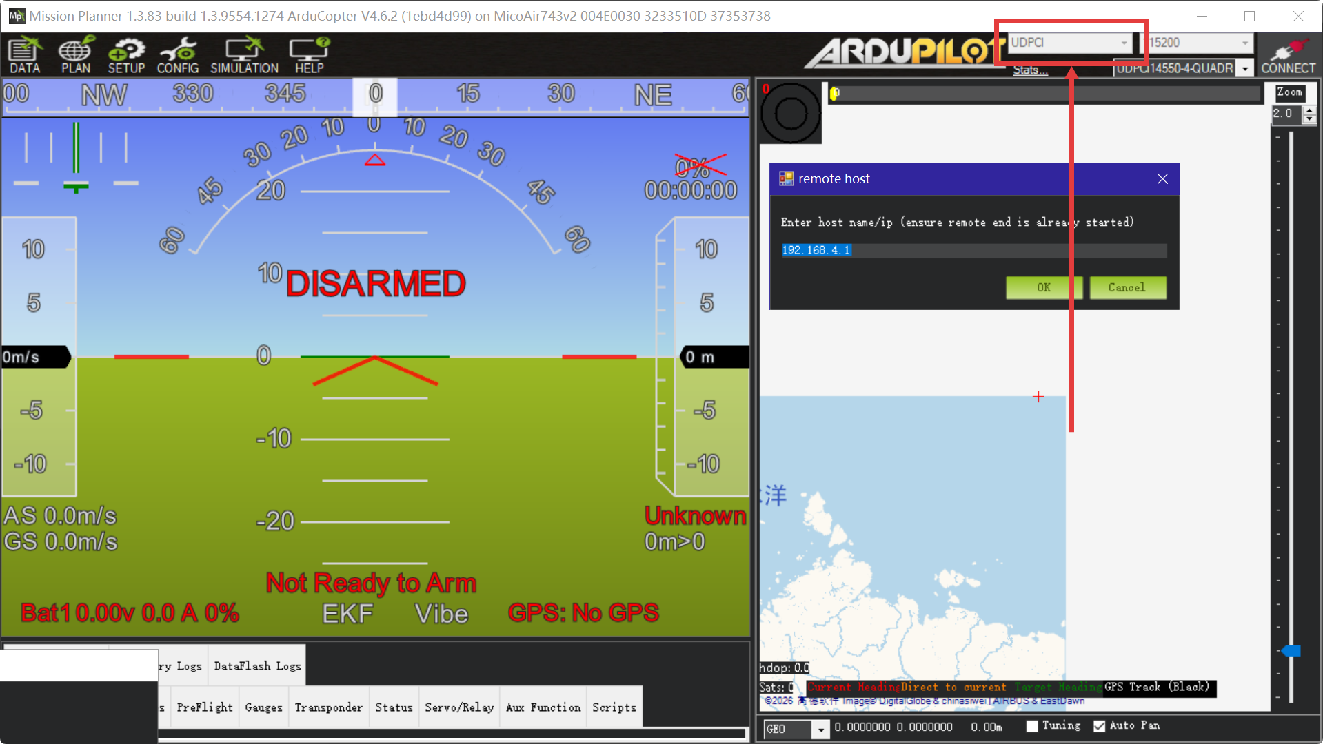
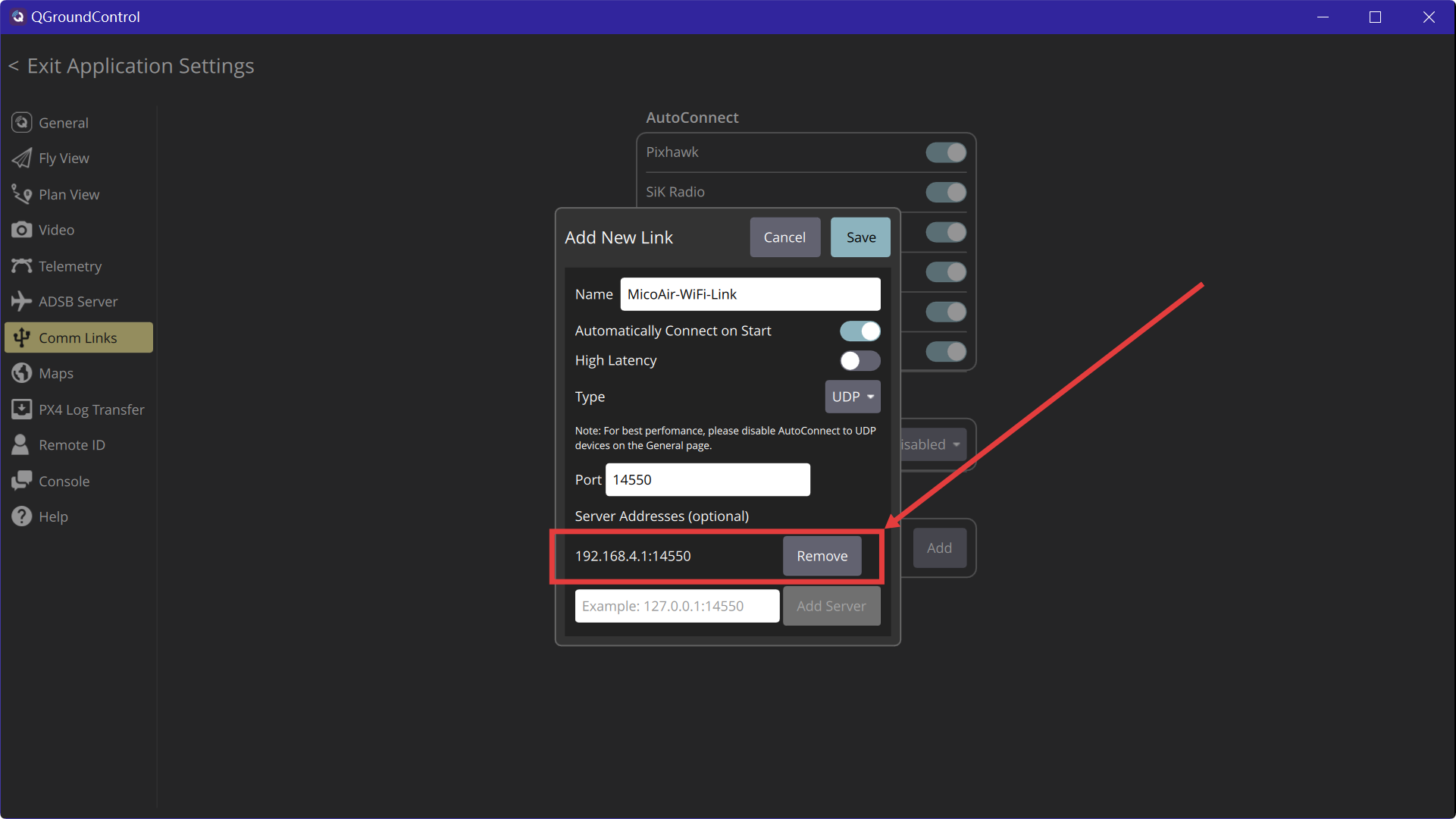
QGroundControl Connection Tutorial (AP Mode)
Open QGC, navigate to Application Settings → Comm Links, and click Add at the bottom to create a new link. Set Type to UDP, Port to 14550, and add the telemetry module’s gateway IP address (192.168.4.1) under Server Addresses. Check Automatically Connect on Start to enable automatic connections for future launches, and click Save.
At the top of the AutoConnect section, check UDP to enable the UDP autoconnect feature; select the newly created link, click Connect, and wait for QGC to establish a connection with the flight controller. The next time you launch QGC, it will automatically connect based on this configured link.
If the connection still fails despite following these steps, consider turning off the Windows Firewall or adding QGC to the firewall’s whitelist.