

Docs directory
Table of contents
MicoAir743-AIO-35A User Manual
Product Overview
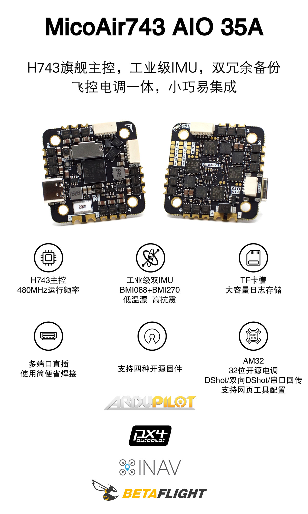
The MicoAir743-AIO-35A combines an H743 flight controller and a 4-in-1 AM32 ESC on one board with a 25.5 × 25.5 mm mounting pattern. The flight controller uses a 480 MHz STM32H743VIH6, dual BMI088 + BMI270 IMUs, a DPS310 barometer, and a microSD card slot. The integrated ESC provides four 35 A AM32 channels.
Key Features
STM32H743VIH6, 480 MHz, 2 MB Flash- Dual
BMI088 + BMI270IMUs andDPS310barometer - microSD card slot
- 7 UARTs, 8 motor outputs, 1 I²C bus, and 1 SWD interface
- LED strip, buzzer, USB Type-C, and BOOT control
- 5 V / 2 A and 12 V / 2 A BEC outputs
- Onboard voltage and current sensing
- 4 × 35 A AM32 4-in-1 ESC supporting PWM, DShot300, DShot600, and bidirectional DShot
- Supports ArduPilot, PX4, INAV, Betaflight, and Skybrush
Purchase
Hardware Specifications
Flight Controller
| Item | Specification |
|---|---|
| Main MCU | STM32H743VIH6, 480 MHz, 2 MB Flash |
| IMU | Dual BMI088 + BMI270 IMUs |
| Barometer | DPS310 |
| Magnetometer | No onboard magnetometer; supports an external I²C magnetometer |
| Analog OSD | None; digital video uses MSP DisplayPort |
| Log storage | microSD card slot |
| UART | 7: UART1, UART2, UART3, UART4, UART6, UART7, UART8 |
| PWM | M1–M8; hardware supports DShot / bidirectional DShot, with final capability determined by firmware |
| Peripheral interfaces | 1 I²C, 1 SWD, 2 ADC, LED strip, buzzer |
| USB | USB Type-C |
ESC
| Item | Specification |
|---|---|
| ESC MCU | AT32F421 |
| ESC firmware | AM32_MICOAIR_743_AIO_F421_2.17 |
| PWM frequency | 48 kHz |
| Supported protocols | PWM, DShot300, DShot600, bidirectional DShot, serial telemetry |
| Continuous current | 35 A × 4; adequate cooling is required |
| Battery input | 3–6S, approximately 10–27 V |
| Configuration tool | AM32 Configurator |
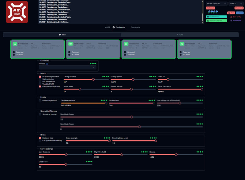
The 35 A continuous-current rating depends on propeller airflow, ambient temperature, and cooling conditions.
Power
| Item | Specification |
|---|---|
| Main power input | 3–6S, approximately 10–27 V |
| 5 V BEC | 2 A maximum |
| 12 V BEC | 2 A maximum, for DJI O3 / Vista and similar devices |
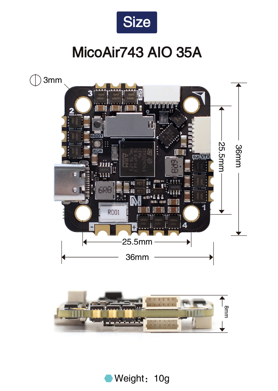
| Mounting-hole spacing | 25.5 × 25.5 mm |
| Mounting-hole diameter | Φ3 mm |
| Dimensions | 36 × 36 × 8 mm |
| Weight | 10 g |
Voltage and Current Scaling
| Parameter | ArduPilot | PX4 | Betaflight | INAV |
|---|---|---|---|---|
| Voltage Factor | 21.12 | 21.12 | 211 | 211 |
| Current Factor | 14.14 | 14.14 | 707 | 707 |
Dimensions and Installation
| Item | Specification |
|---|---|
| Mounting-hole spacing | 25.5 × 25.5 mm |
| Mounting-hole diameter | Φ3 mm |
| Dimensions | 36 × 36 × 8 mm |
| Weight | 10 g |
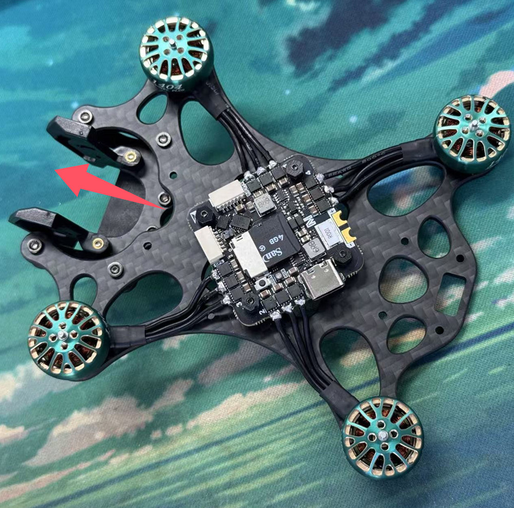
- The board arrow points toward the aircraft nose by default, with the component-label side facing upward.
- Use insulated vibration-damping standoffs. Do not allow screws or carbon-fiber plates to contact pads or components.
- Keep the ESC MOSFET area ventilated; do not fully cover it with foam, double-sided tape, or wiring.
Interfaces and Power
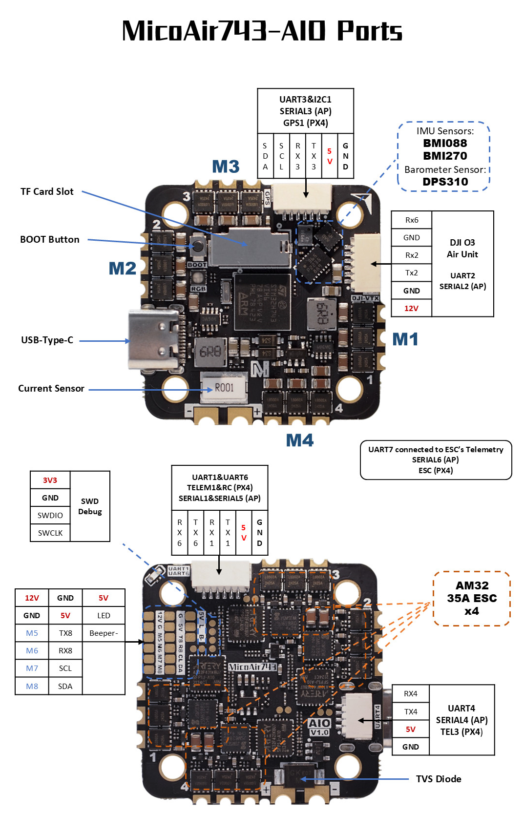
Interface Definition
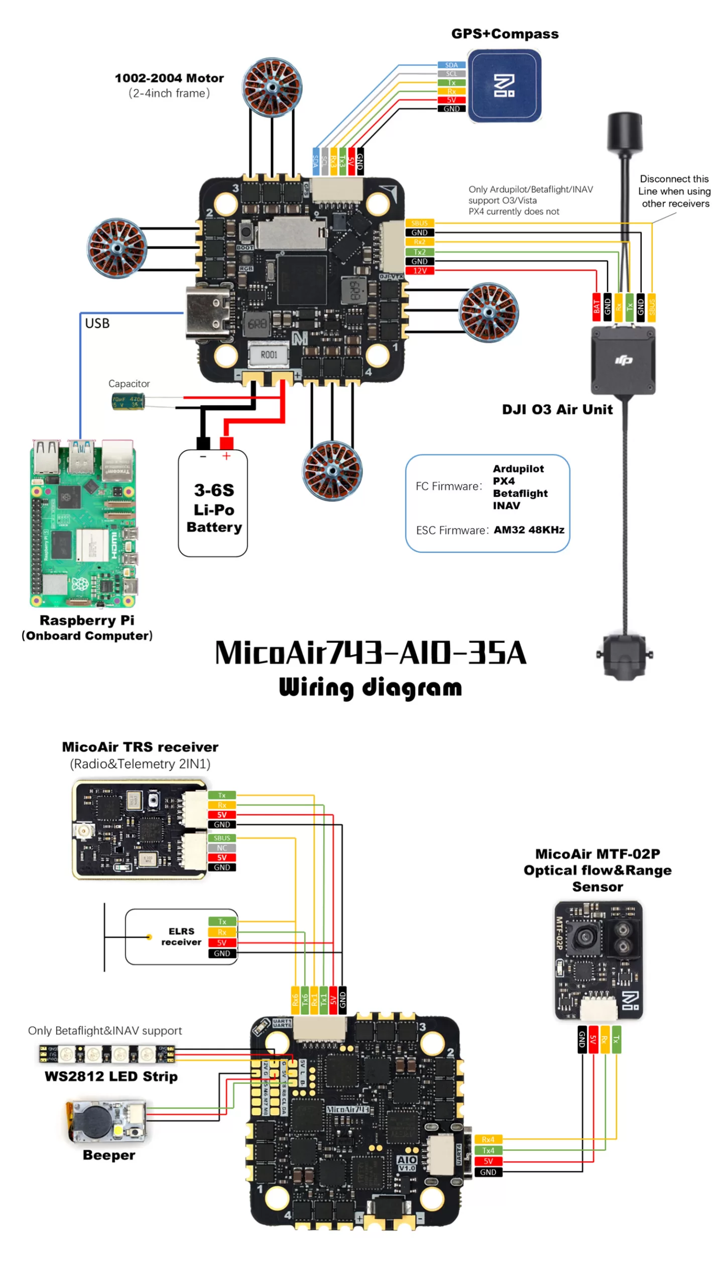
Typical Wiring
Power Rules
| Interface | Voltage | Typical use | Notes |
|---|---|---|---|
VBAT | 3–6S, approximately 10–27 V | Main power for the flight controller and 4-in-1 ESC | Never reverse the polarity |
5V | 5 V | Receiver, GPS, optical flow, and other peripherals | Total load must not exceed 2 A |
12V | 12 V | DJI O3 / Vista, cameras, and similar devices | Do not connect 5 V peripherals |
GND | 0 V | Power and signal reference ground |
Pin 1 on the SH1.0-6P digital-video connector is 12 V. Verify connector orientation and pin order against the interface diagram.
Serial-Port Mapping
ArduPilot Serial-Port Mapping
| ArduPilot port | Physical interface | Default use / Feature |
|---|---|---|
SERIAL0 | USB | USB virtual serial port |
SERIAL1 | UART1 | MAVLink2, DMA capable |
SERIAL2 | UART2 | VTX-HD / DisplayPort, DMA capable |
SERIAL3 | UART3 | GPS, DMA capable |
SERIAL4 | UART4 | MAVLink2, DMA capable |
SERIAL5 | UART6 | RC input, DMA capable |
SERIAL6 | UART7 | Internal ESC telemetry, DMA capable |
SERIAL7 | UART8 | General-purpose serial port, DMA capable |
PX4 Serial-Port Mapping
| PX4 device | PX4 interface name | Physical interface |
|---|---|---|
ttyACM0 | USB | USB virtual serial port |
ttyS0 | TELEM1 | UART1 |
ttyS1 | TELEM2 | UART2 |
ttyS2 | GPS1 | UART3 |
ttyS3 | TELEM3 | UART4 |
ttyS4 | RC | UART6 |
ttyS5 | ESC | UART7, internal ESC telemetry |
ttyS6 | TELEM4 | UART8 |
PWM Outputs
All eight M1–M8 outputs support DShot and bidirectional DShot. Actual support depends on the flight-controller firmware.
| Group | Channels | Description |
|---|---|---|
| Group 1 | PWM1, PWM2, PWM3, PWM4 | Channels in the group normally use compatible protocols and frequencies |
| Group 2 | PWM5, PWM6 | Same group constraint |
| Group 3 | PWM7, PWM8 | Same group constraint |
Outputs in one timer group cannot use arbitrary combinations of different protocols or frequencies.
Receiver
UART6 is the default RC input. Connect an SBUS signal to RX6. CRSF/ELRS normally uses both TX6 and RX6.
| Protocol | Recommended wiring | Notes |
|---|---|---|
| SBUS | Signal → RX6 | One-way signal |
| CRSF / ELRS | Receiver TX → RX6; receiver RX → TX6 | Supports telemetry |
| FPort | Signal → TX6 | Single-wire bidirectional protocol |
| DSM / SRXL | Signal → RX6 | Verify the supply voltage |
| PPM | Not supported | Use a serial receiver |
ArduPilot can assign RC input to another UART. Set the target
SERIALn_PROTOCOLto23, reassign the originalSERIAL5_PROTOCOL, and verify failsafe operation after the change.
OSD and Digital Video
The board has no AT7456E analog OSD. Digital video uses MSP DisplayPort on UART2:
- ArduPilot can use
OSD_TYPE = 5 - The SH1.0-6P connector provides 12 V
- DJI OSD capability in PX4 varies by version; refer to the applicable PX4 documentation
Do not connect the 12 V pin on the video connector to a 5 V camera, receiver, or ordinary serial peripheral.
Flight Controller Firmware
MicoConfigurator is a browser-based flight-controller configuration tool for Windows, macOS, and Linux. It supports configuration and debugging, plus online, local-file, and DFU firmware updates.
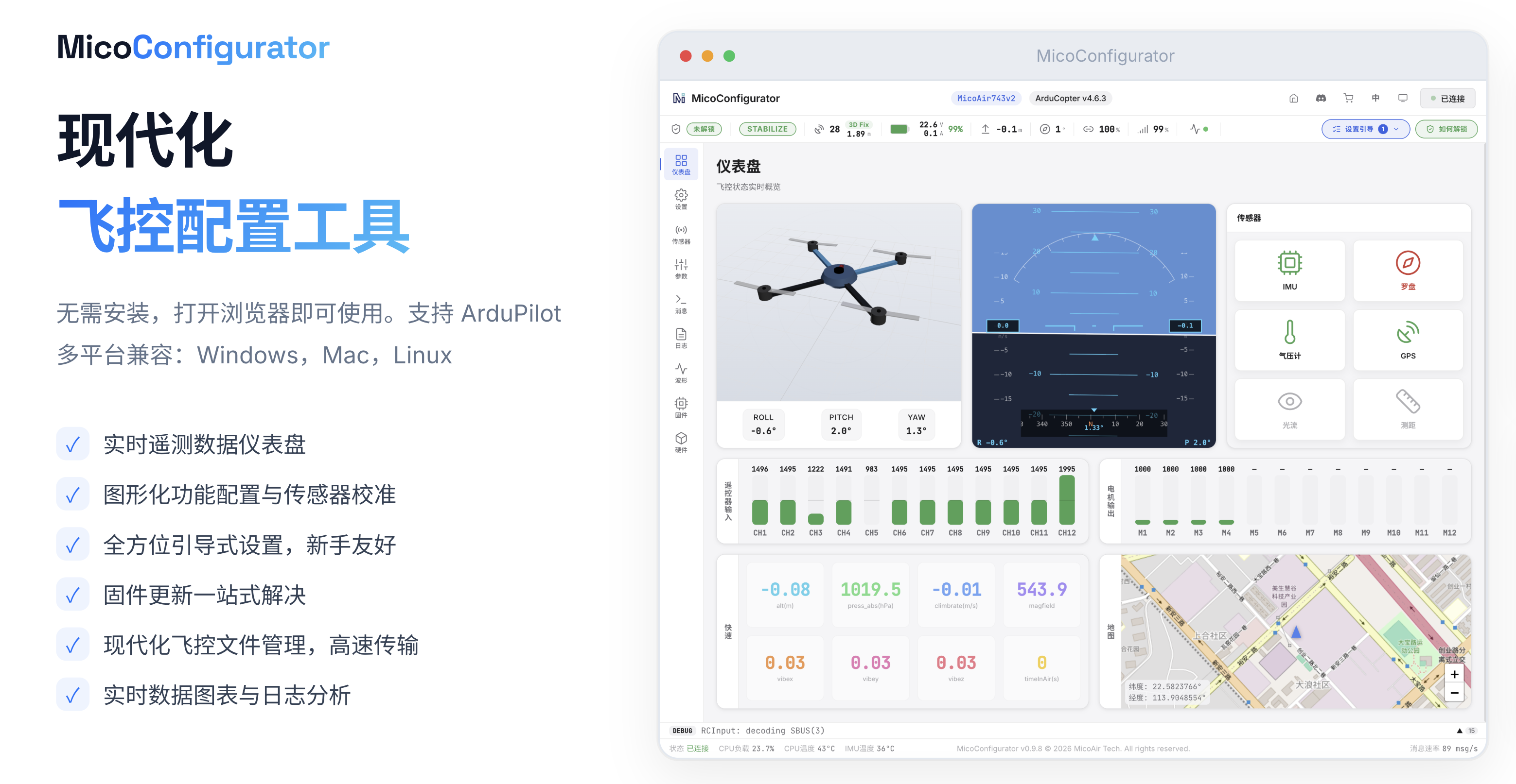
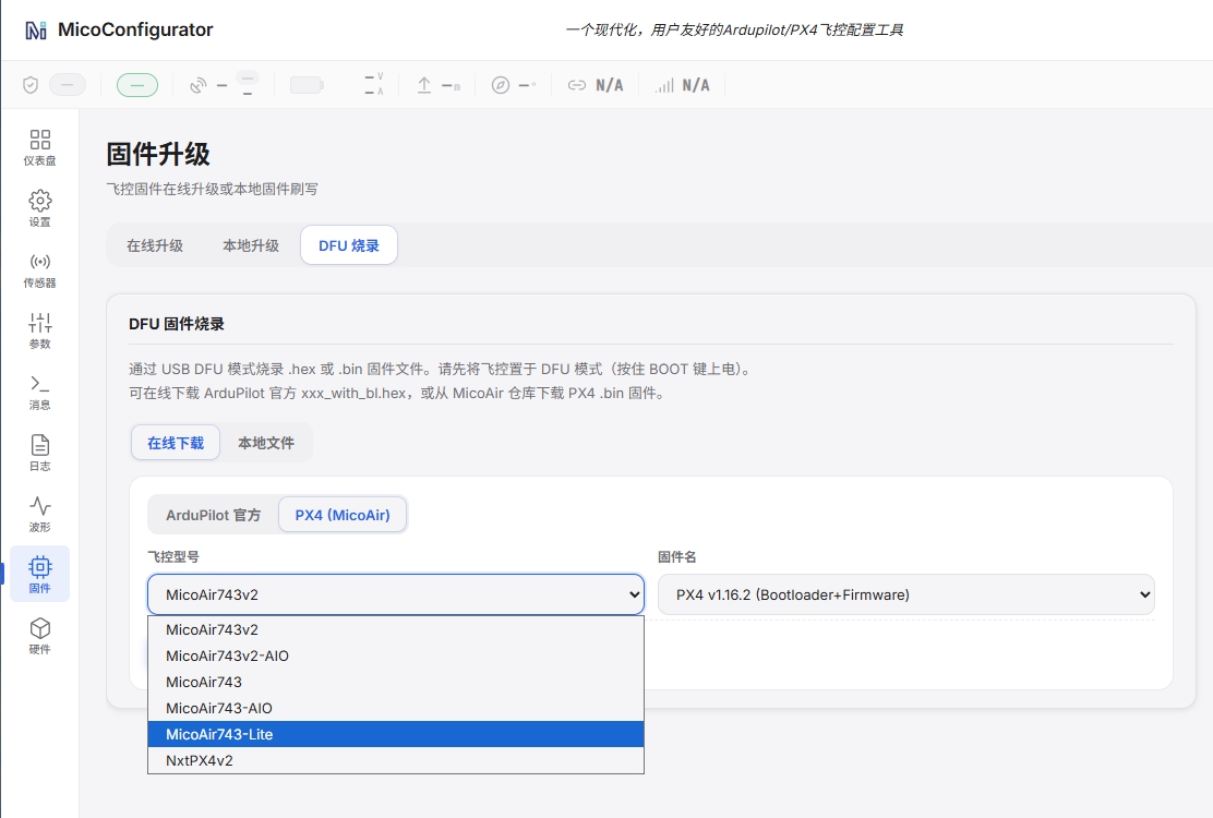
Open MicoConfigurator in Chrome or Edge. In DFU mode, select the board and firmware directly in the browser (Windows requires a DFU driver).
ArduPilot
- Firmware target:
MicoAir743-AIO - Included in the official hardware support list from ArduPilot 4.6.0
- Official ArduPilot hardware definition
- Official ArduPilot firmware downloads
- ArduPilot Custom Firmware Builder
- Historical firmware
PX4
- Firmware target:
micoair_h743-aio - Included in the official hardware support list from PX4 1.16.0
- Official PX4 hardware definition
- Historical firmware
Official PX4 firmware build guide
Build the bootloader:
make micoair_h743-aio_bootloader
Build the default firmware:
make micoair_h743-aio_default
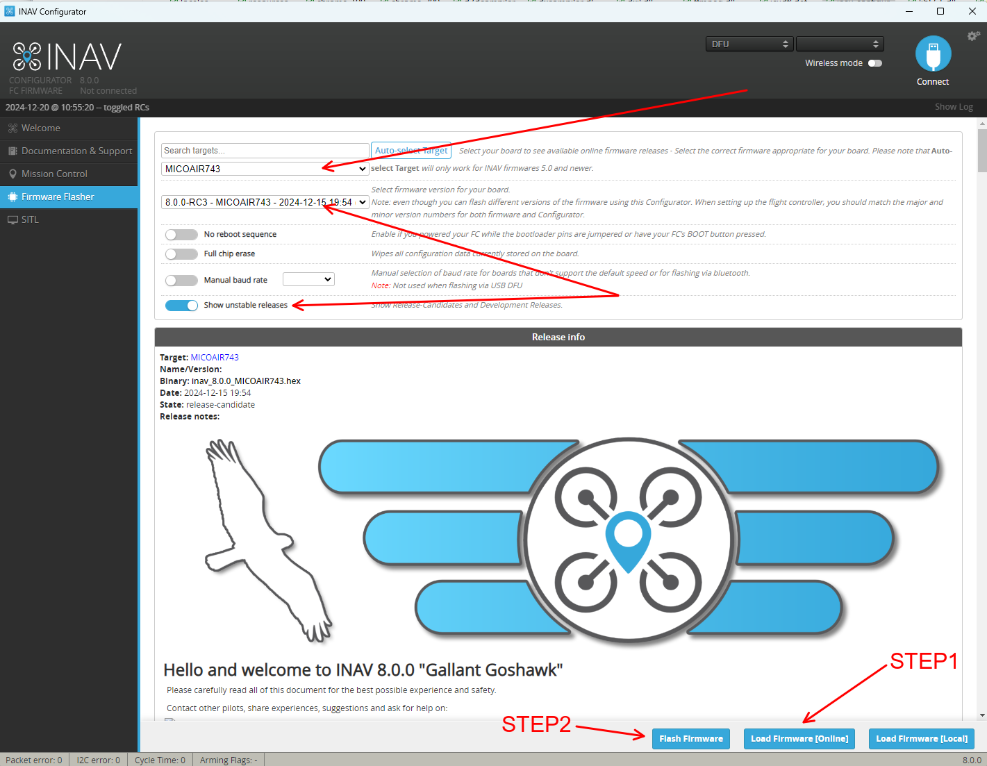
INAV
- Firmware target:
MICOAIR743-AIO - Included in the official support list from INAV 8.0.0
- Official INAV repository
Betaflight
- Firmware target:
MICOAIR743 - MicoAir743 is supported from Betaflight 4.5.0
- The original product documentation states that the Betaflight target reserves buzzer and LED-strip resources that match this AIO
- Betaflight MICOAIR743 configuration
Skybrush
- Drone-swarm firmware based on ArduPilot
- MicoAir743-AIO Skybrush firmware
Related Resources
- MicoConfigurator
- Flight Controller Firmware Flashing Guide
- ArduPilot Basic Configuration Guide
- Connect a MicoAir H743V2/Lite to a Computer over Bluetooth
- Official ArduPilot documentation
- Official PX4 documentation
- QGroundControl downloads
- INAV Configurator
- Betaflight Configurator
Appendix A: Pinout Table
| Category | Device / Use | Bus / Peripheral | Signal | MCU pin |
|---|---|---|---|---|
| IMU | BMI270 | SPI2 | MOSI | PC3 |
| IMU | BMI270 | SPI2 | MISO | PC2 |
| IMU | BMI270 | SPI2 | SCLK | PD3 |
| IMU | BMI270 | GPIO | CS | PA15 |
| IMU | BMI088 | SPI2 | MOSI | PC3 |
| IMU | BMI088 | SPI2 | MISO | PC2 |
| IMU | BMI088 | SPI2 | SCLK | PD3 |
| IMU | BMI088 | GPIO | GYRO_CS | PD5 |
| IMU | BMI088 | GPIO | ACCEL_CS | PD4 |
| Barometer | DPS310 | I²C2 | SCL | PB10 |
| Barometer | DPS310 | I²C2 | SDA | PB11 |
| Motor output | PWM | TIM1 / CH4 | M1 | PE14 |
| Motor output | PWM | TIM1 / CH3 | M2 | PE13 |
| Motor output | PWM | TIM1 / CH2 | M3 | PE11 |
| Motor output | PWM | TIM1 / CH1 | M4 | PE9 |
| Motor output | PWM | TIM3 / CH4 | M5 | PB1 |
| Motor output | PWM | TIM3 / CH3 | M6 | PB0 |
| Motor output | PWM | TIM4 / CH1 | M7 | PD12 |
| Motor output | PWM | TIM4 / CH2 | M8 | PD13 |
| LED strip | LED | TIM4 / CH3 | LED | PD14 |
| Buzzer | Beeper | TIM4 / CH4 | B- | PD15 |
| External oscillator | External | 8 MHz | OSC_IN | PH0 |
| External oscillator | External | 8 MHz | OSC_OUT | PH1 |
| Status LED | GPIO_OUTPUT | RED | — | PE5 |
| Status LED | GPIO_OUTPUT | BLUE | — | PE4 |
| Status LED | GPIO_OUTPUT | GREEN | — | PE6 |
| Button | — | BOOT | — | BOOT0 |
| I²C | Peripheral connector | I²C1 | SDA | PB7 |
| I²C | Peripheral connector | I²C1 | SCL | PB6 |
| UART | UART1 | UART1 | TX | PA9 |
| UART | UART1 | UART1 | RX | PA10 |
| UART | VTX-HD | UART2 | TX | PA2 |
| UART | VTX-HD | UART2 | RX | PA3 |
| UART | GPS | UART3 | TX | PD8 |
| UART | GPS | UART3 | RX | PD9 |
| UART | UART4 | UART4 | TX | PA0 |
| UART | UART4 | UART4 | RX | PA1 |
| UART | RCIN | UART6 | TX | PC6 |
| UART | RCIN | UART6 | RX | PC7 |
| UART | ESC telemetry | UART7 | RX | PE7 |
| UART | UART8 | UART8 | TX | PE1 |
| UART | UART8 | UART8 | RX | PE0 |
| USB | USB | USB | USB_DM | PA11 |
| USB | USB | USB | USB_DP | PA12 |
| SD card | microSD | SDMMC1 | D0 | PC8 |
| SD card | microSD | SDMMC1 | D1 | PC9 |
| SD card | microSD | SDMMC1 | D2 | PC10 |
| SD card | microSD | SDMMC1 | D3 | PC11 |
| SD card | microSD | SDMMC1 | CLK | PC12 |
| SD card | microSD | SDMMC1 | CMD | PD2 |
| Debug interface | SWD | SWD | SWDIO | PA13 |
| Debug interface | SWD | SWD | SWCLK | PA14 |
| Battery sensing | Divider ratio approximately 1:21 | ADC | Voltage | PC0 |
| Current sensing | Onboard current sensor | ADC | Current | PC1 |