

Docs directory
Table of contents
MicoAir743v3 Flight Controller User Manual
Product Overview
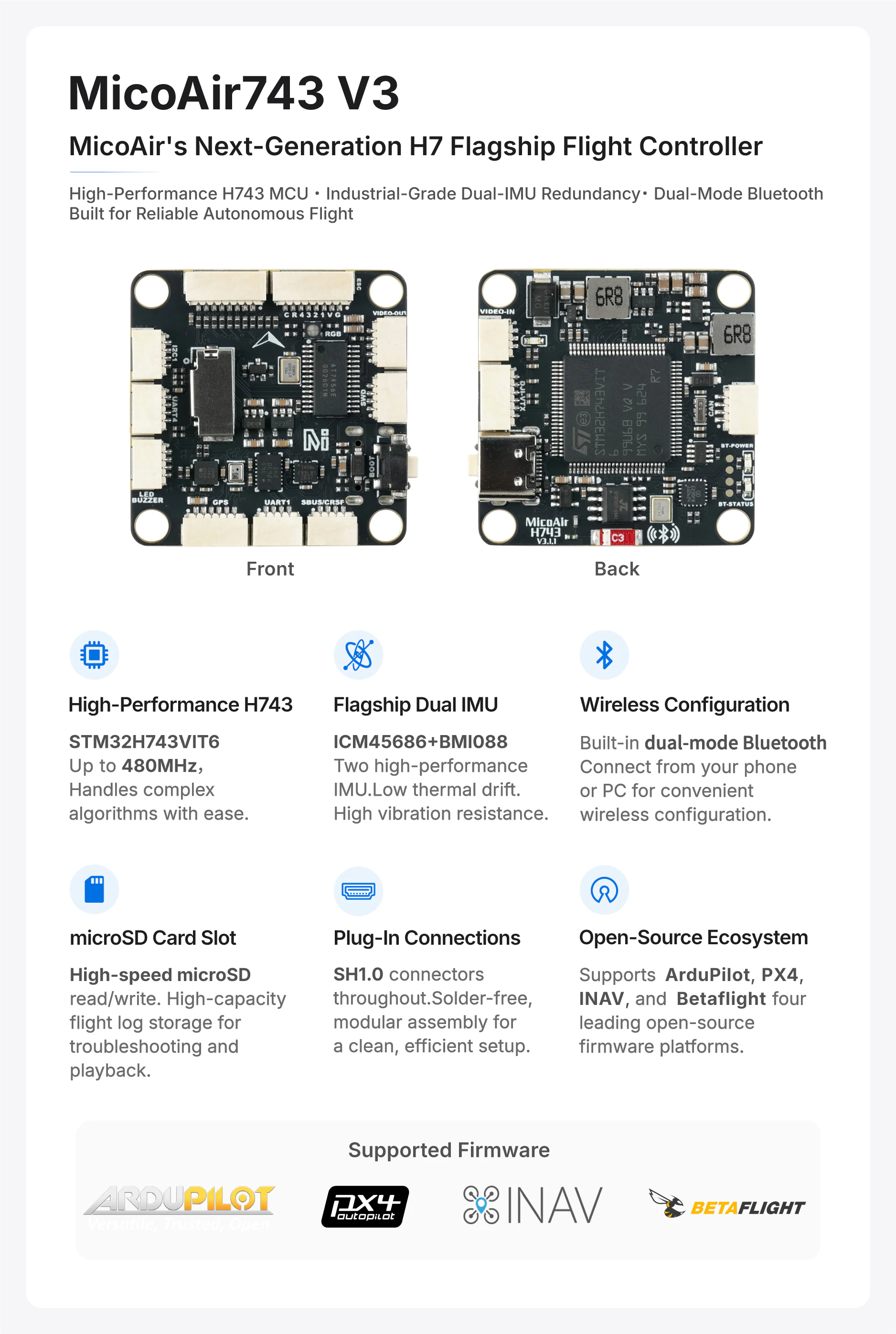
MicoAir743v3 is MicoAir Tech's next-generation flagship H7 flight controller for multirotors and autonomous flight platforms, building on the MicoAir743v2. It features a 480 MHz STM32H743VIT6 MCU, dual high-performance IMUs (BMI088 + ICM45686), a SPA06 barometer, an onboard IST8310 magnetometer, an AT7456E analog OSD chip, and a microSD card slot for flight logs.
The controller provides 7 UARTs, 11 PWM outputs, 1 CAN interface, 1 I²C interface, two BEC outputs, a digital video transmitter (VTX) interface, and onboard dual-mode Bluetooth telemetry. It supports open-source firmware including ArduPilot, PX4, INAV, and Betaflight.
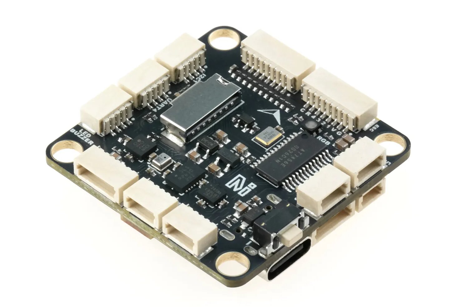
Compared with v2, MicoAir743v3 features upgraded sensors for improved performance and adds a CAN interface for the growing range of CAN peripherals. The SD card interface has been optimized to meet the high-speed storage requirements of certain firmware platforms. The onboard Bluetooth module now supports both SPP and BLE for more convenient connectivity. The power circuitry has also been refined, with switchable 9 V power for the VTX.
Key Features
STM32H743VIT6, 480 MHz, 2 MB Flash- Dual IMUs:
BMI088 + ICM45686 SPA06barometer and onboardIST8310magnetometerAT7456Eanalog OSD and MSP DisplayPort support for digital FPV systems- 7 UARTs, 11 PWM outputs, 1 CAN interface, 1 I²C interface, and 1 SWD interface
- microSD card slot for flight log storage
- Onboard SPP/BLE dual-mode Bluetooth telemetry, internally connected to UART8 at a default baud rate of
115200 - Two BEC outputs: 4.6 V / 2 A and 9 V / 2 A; the 9 V output supports GPIO-controlled switching
- 2–6S battery input, 6–27 V
- Support for ArduPilot, PX4, INAV, and Betaflight firmware
Purchase
MicoAir Tech Store
Hardware Specifications
Processor and Sensors
| Item | Specification |
|---|---|
| MCU | STM32H743VIT6, 480 MHz, 2 MB Flash |
| IMUs | Dual IMUs: BMI088 + ICM45686 |
| Barometer | SPA06 |
| Onboard magnetometer | IST8310 |
| Analog OSD | AT7456E |
| Log storage | microSD card slot |
Interfaces and Outputs
| Item | Count / Description |
|---|---|
| UART | 7; UART8 is internally connected to onboard Bluetooth, and UART7 exposes RX only for ESC telemetry |
| PWM | 11 outputs; PWM1–PWM8 support DShot and bidirectional DShot, subject to firmware support |
| CAN | 1 |
| I²C | 1 |
| SWD | 1 |
| ADC | 2 inputs: battery voltage and current sensing |
| USB | USB Type-C |
| Digital video | DJI O3/O4-compatible interface with MSP DisplayPort support |
| Receiver | UART6 is the default RC input; other UARTs can also be used with ArduPilot |
| Other | Buzzer, addressable LEDs, and BOOT button/pads |
Power and Dimensions
| Item | Specification |
|---|---|
| Battery input | 2–6S, 6–27 V |
| 4.6 V BEC | Up to 2 A for receivers, GPS modules, optical flow sensors, and other peripherals |
| 9 V BEC | Up to 2 A for VTXs, cameras, and other peripherals; GPIO-controlled switching supported |
| Mounting hole spacing | 30.5 × 30.5 mm |
| Mounting hole diameter | 4 mm |
| Dimensions | 36 × 36 × 8 mm |
| Weight | 10 g |
Dimensions and Installation
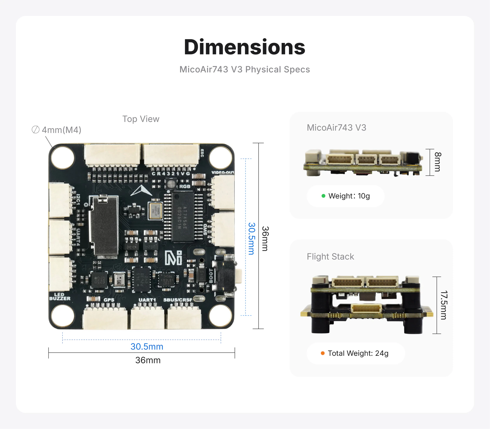
Follow these guidelines when installing the flight controller:
- Use the 30.5 × 30.5 mm mounting pattern. Ensure that screws and washers do not contact components on the board.
- Use vibration-damping mounts where possible. Tighten them evenly without bending the board.
- Point the arrow on the flight controller toward the front of the aircraft. If the installation requires a different orientation, set the corresponding board orientation parameters in the firmware.
Interfaces and Power Supply
Connector Pinouts
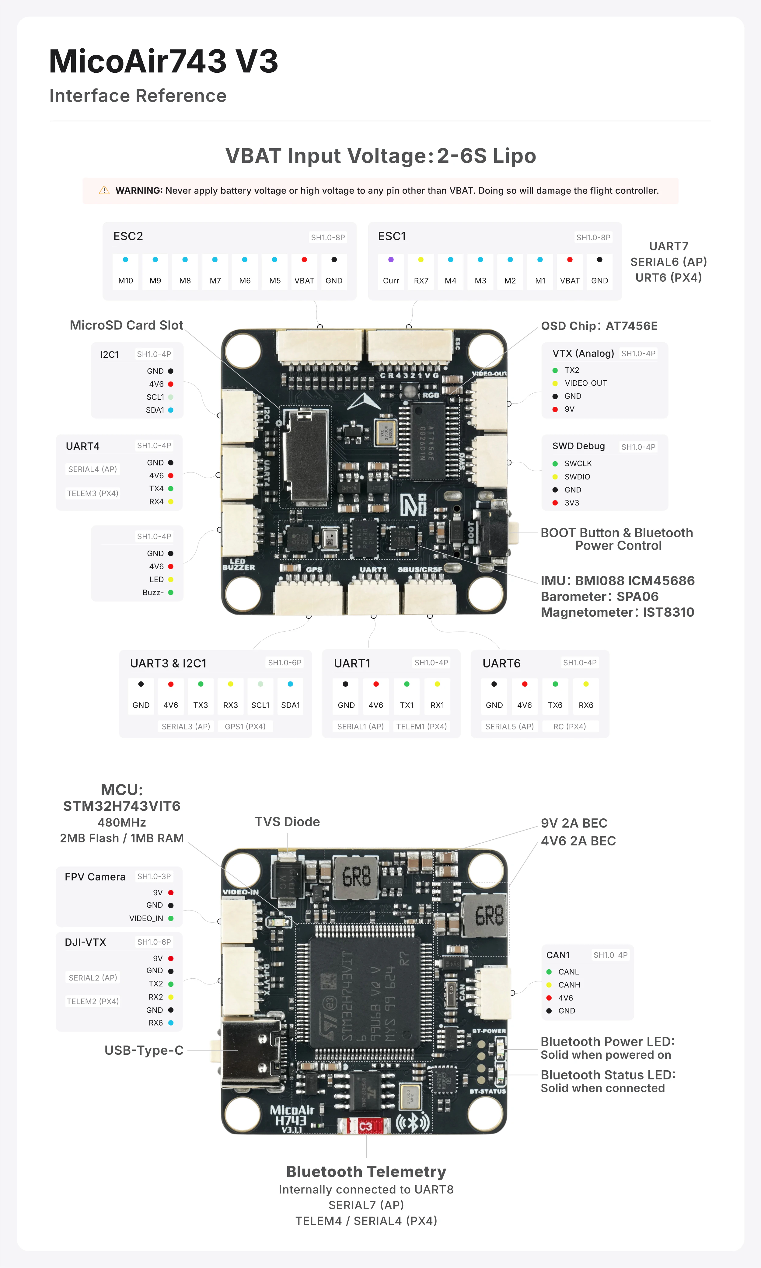
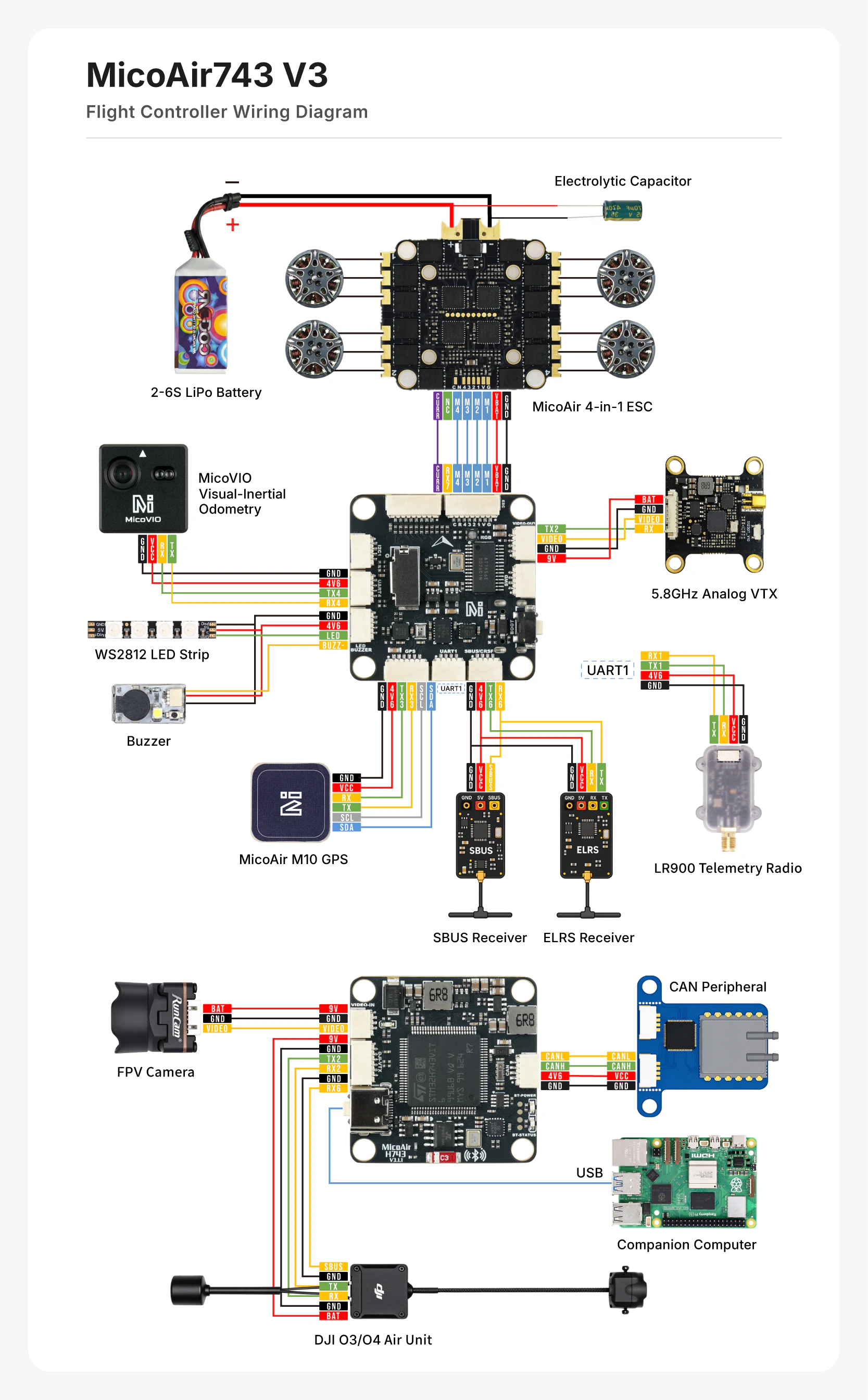
Typical Wiring
Power Connections
| Pin | Voltage | Typical Use | Notes |
|---|---|---|---|
VBAT | 6–27 V | Main power input for the flight controller | Connect only a 2–6S battery or an equivalent power supply |
4V6 | 4.6 V | Power for receivers, GPS modules, optical flow sensors, rangefinders, and other peripherals | |
9V | 9 V | Power for DJI air units, cameras, and other peripherals | Do not connect devices rated for 5 V only |
GND | 0 V | Common ground for power and signals |
Pin 1 of the digital video connector supplies 9 V. Before connecting a DJI O3/O4 air unit or another VTX, verify the pin order and the device's input voltage requirements. Do not connect 9 V to a receiver, GPS module, or camera rated for 5 V only.
Serial communication usually requires
TX,RX, andGND. Connect the flight controller'sTXto the peripheral'sRX, and itsRXto the peripheral'sTX. For a unidirectional protocol, connect only the signal line required by that protocol, along with the appropriate ground connection.
Serial Port Mapping
ArduPilot Serial Port Mapping
| ArduPilot Port | Physical Interface | Default Function / Features |
|---|---|---|
SERIAL0 | USB | USB virtual serial port |
SERIAL1 | UART1 | MAVLink2, DMA supported |
SERIAL2 | UART2 | DisplayPort, DMA supported |
SERIAL3 | UART3 | GPS, DMA supported |
SERIAL4 | UART4 | MAVLink2, DMA supported |
SERIAL5 | UART6 | RC input, DMA supported |
SERIAL6 | UART7 | ESC telemetry, DMA supported |
SERIAL7 | UART8 | Onboard Bluetooth telemetry, DMA supported |
PX4 Serial Port Mapping
| PX4 Device | PX4 Port Name | Physical Interface |
|---|---|---|
ttyACM0 | USB | USB virtual serial port |
ttyS0 | TELEM1 | UART1 |
ttyS1 | TELEM2 | UART2 |
ttyS2 | GPS1 | UART3 |
ttyS3 | TELEM3 | UART4 |
ttyS4 | RC | UART6 |
ttyS5 | URT6 | UART7 |
ttyS6 | TELEM4 / SERIAL4 | UART8 |
UART8 is used by the onboard Bluetooth module. Its default baud rate is
115200.
PWM Outputs
MicoAir743v3 provides up to 11 PWM outputs: 10 motor outputs and one output shared with the LED function. PWM1–PWM8 have hardware support for DShot and bidirectional DShot; availability depends on the installed firmware and its version.
PWM Timer Groups
| Group | Channels | Notes |
|---|---|---|
| Group 1 | PWM1, PWM2, PWM3, PWM4 | Channels in the same group generally require compatible output protocols and rates |
| Group 2 | PWM5, PWM6 | The same timer-group restrictions apply |
| Group 3 | PWM7, PWM8, PWM11 | PWM11 is also used for addressable LEDs |
| Group 4 | PWM9, PWM10 | The same timer-group restrictions apply |
Different output protocols generally cannot be mixed arbitrarily within the same timer group. When changing the PWM protocol, output rate, or addressable LED configuration, check all channels in that group together.
When PWM11 is configured for addressable LEDs, PWM7 and PWM8 are subject to the same timer-group restrictions and may also be limited to LED-compatible configurations. Follow the output grouping rules for your installed firmware.
ESC Protocol Recommendations
- Standard PWM ESCs: select a standard PWM protocol supported by the firmware.
- DShot ESCs:
DShot300is generally a good starting point, balancing reliability and bandwidth. - Bidirectional DShot: both the flight controller firmware and ESC firmware must support it.
Remove all propellers before testing motors. Verify motor numbering, rotation direction, and failsafe behavior before reinstalling the propellers and proceeding with controlled ground tests.
Receivers
UART6 is the default RC input. With ArduPilot, other available UARTs can also be configured according to the receiver protocol's requirements.
| Protocol | Recommended Wiring | Notes |
|---|---|---|
| SBUS | Receiver signal → RX6 | Usually requires one signal wire, plus ground and power |
| DSM / SRXL | Receiver signal → RX6 | Supply power at the voltage required by the receiver |
| FPort | Receiver signal → TX6 | Single-wire, half-duplex protocol |
| CRSF / ELRS | Receiver TX → RX6; receiver RX → TX6 | Supports telemetry over CRSF when correctly configured |
| SRXL2 | Receiver signal → TX6 | In ArduPilot, set SERIAL5_PROTOCOL = 23 and SERIAL5_OPTIONS = 4 |
| PPM | Not supported | Use a serial receiver protocol instead |
If a CRSF/ELRS receiver is not detected, first check that TX and RX are crossed correctly, the supply voltage is correct, and UART6 is not assigned to another function. Do not identify pins by wire color alone.
OSD and Video Interfaces
MicoAir743v3 provides both AT7456E analog OSD and MSP DisplayPort support for digital FPV systems such as DJI O3/O4.
Analog OSD
- Onboard chip:
AT7456E - In ArduPilot, set
OSD_TYPE = 1to enable the MAX7456-compatible driver. - Before use, check the camera's video standard, video input/output wiring, and firmware support.
MSP DisplayPort / DJI O3/O4
- Connect the digital VTX using the SH1.0-6P connector.
- UART2 is used for MSP DisplayPort by default.
- The video connector supplies 9 V.
- OSD features and configuration procedures vary by firmware version. Refer to the documentation for your installed firmware.
Before connecting the VTX, confirm again that pin 1 supplies 9 V. Incorrect wiring can damage both the VTX and the flight controller.
Battery Monitoring, Magnetometer, and I²C
Battery Voltage and Current Monitoring
The flight controller has onboard voltage sensing and receives the current sensor signal through the ESC connector. It supports batteries up to 6S.
The default parameters in the official ArduPilot hardware definition are listed below:
| Parameter | Default Value | Function |
|---|---|---|
BATT_VOLT_PIN | 10 | Voltage-sensing ADC input |
BATT_CURR_PIN | 11 | Current-sensing ADC input |
BATT_VOLT_MULT | 21.2 | Voltage divider multiplier |
BATT_AMP_PERVLT | 40.2 | Current sensor scaling factor (A/V) |
The current sensor scaling factor depends on the sensor circuitry in the ESC. The values above are MicoAir743v3 defaults and are not suitable for every ESC. Adjust them for the hardware you are using.
Magnetometer
- Onboard magnetometer:
IST8310 - An external magnetometer can be connected to the I²C
SDA/SCLpins. - High-current wiring, buzzers, magnets, and motors can cause magnetic interference.
For applications requiring greater heading accuracy, use an external GPS/compass module mounted away from the power system, and recalibrate the compass after completing the aircraft assembly.
Connecting via Bluetooth
The onboard Bluetooth telemetry module is internally connected to UART8 at a default baud rate of 115200. It supports both SPP and BLE. SPP offers broad compatibility and can be used with apps such as QGroundControl on Android. BLE provides a quick, convenient connection but requires compatible software. Both MicoConfigurator and MicoPilot support BLE connections to MicoAir743v3, making BLE the generally recommended option.
Bluetooth can be used for ground-based parameter configuration and flight controller status monitoring.
Enabling Bluetooth Power (Enabled by Default)
- Power on the flight controller normally and wait at least 3 seconds.
- Check the blue Bluetooth power LED.
- If the LED is off, press and hold the
BOOTbutton for approximately 2 seconds to turn Bluetooth on. - Press and hold the button again to turn Bluetooth off. The on/off state is retained after power is removed.
Connecting via BLE in MicoConfigurator
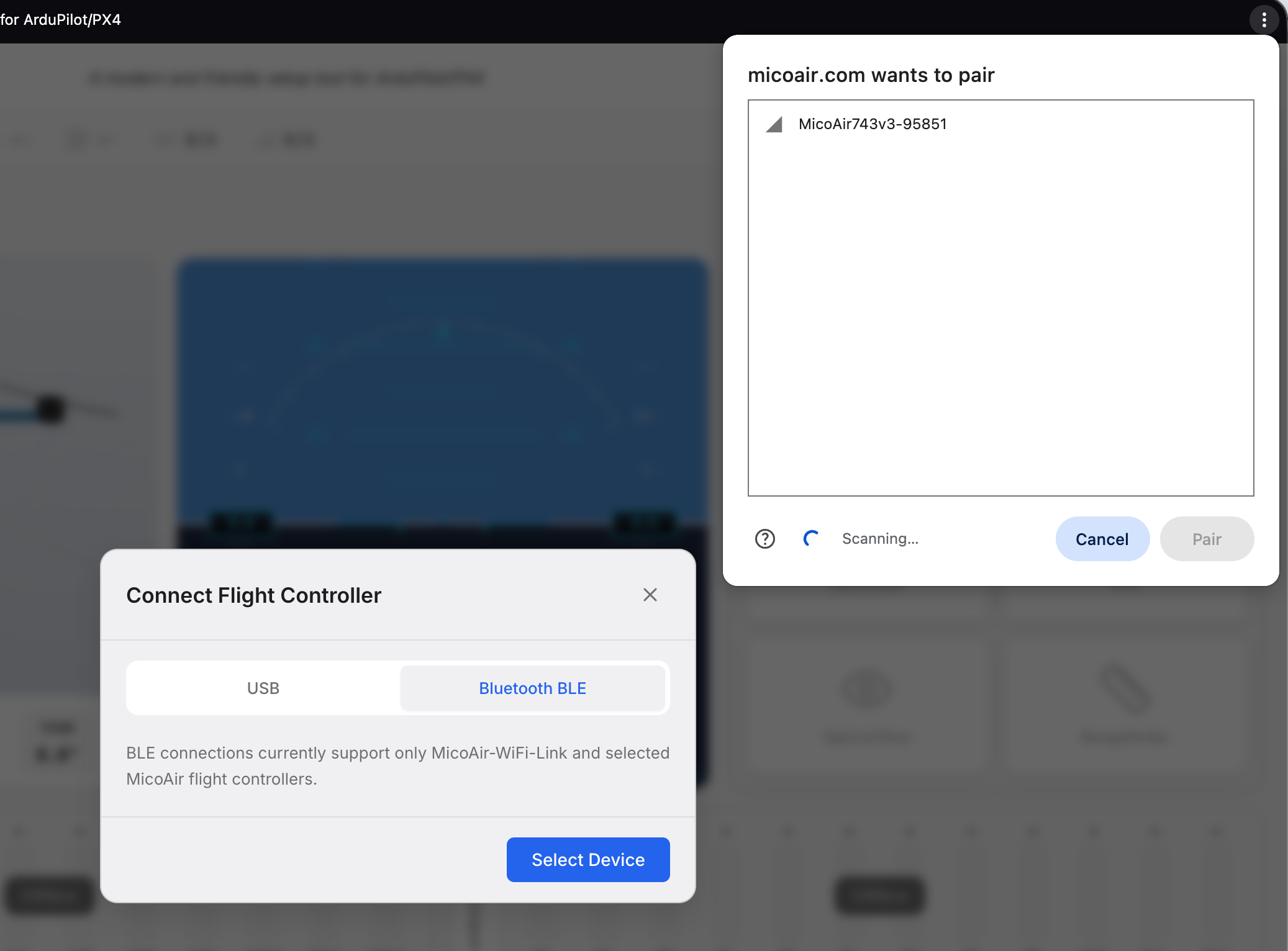
In the connection dialog, select Bluetooth BLE, then click Select Device. In the Bluetooth device picker, select the device named MicoAir743v3-xxxxx and click Pair.
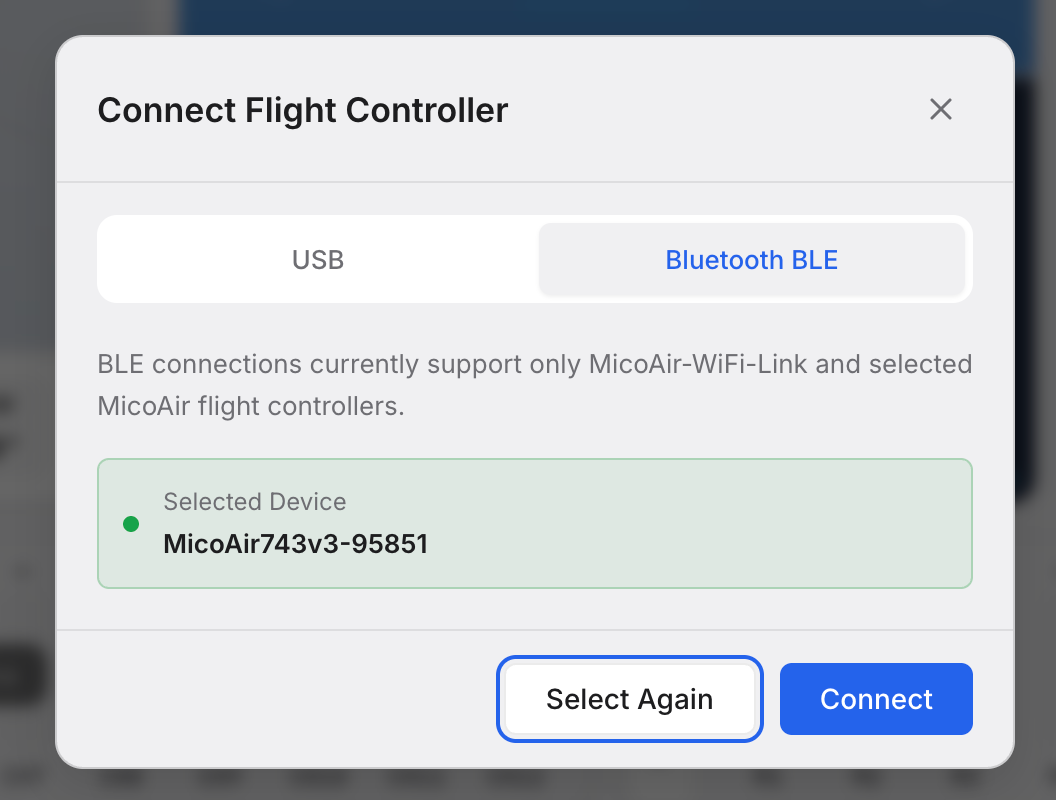
Once paired, the device name appears in the connection dialog. Click Connect. MicoConfigurator will establish the Bluetooth connection and begin loading the flight controller parameters.
The green Bluetooth status LED on the flight controller stays on once the Bluetooth connection is established.
Connecting via BLE in MicoPilot
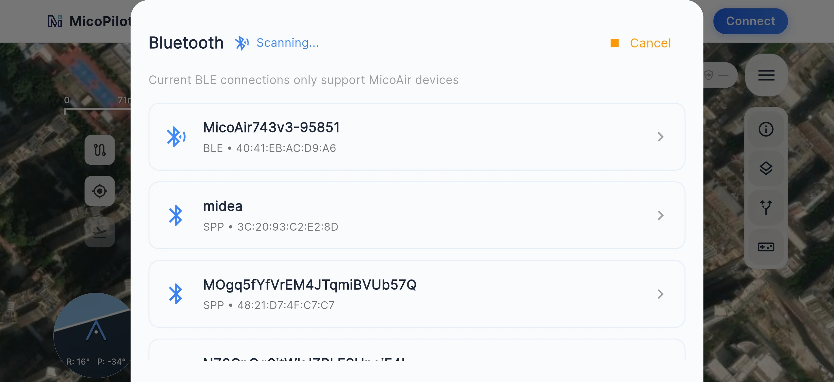
Open MicoPilot, tap Connect in the upper-right corner, and select Bluetooth as the connection method.
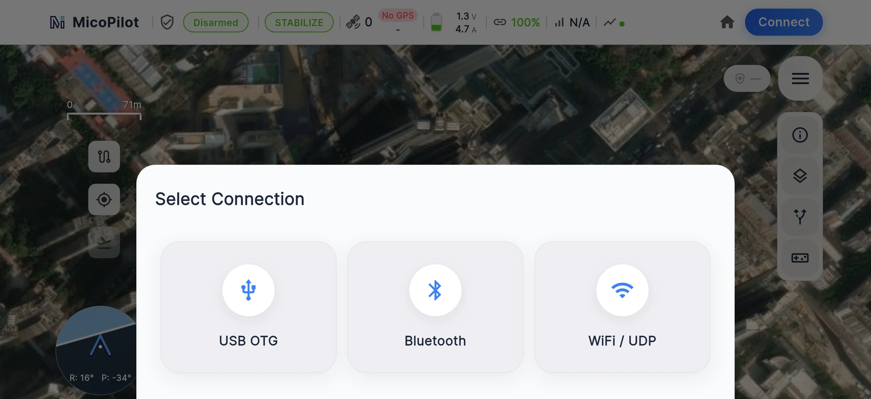
The Bluetooth connection dialog automatically scans for nearby devices. Wait a few seconds, then select MicoAir743v3-xxxxx from the list to pair with it. MicoPilot will automatically connect to the flight controller and begin loading its parameters. This typically takes 4–5 seconds with ArduPilot firmware. Actual connection time may vary.
Flight Controller Firmware
MicoAir743v3 supports ArduPilot, PX4, INAV, and Betaflight.
MicoConfigurator is a browser-based flight controller configuration tool for Windows, macOS, and Linux. It can be used to configure and troubleshoot the flight controller, and to update firmware using online downloads, local files, or DFU mode.
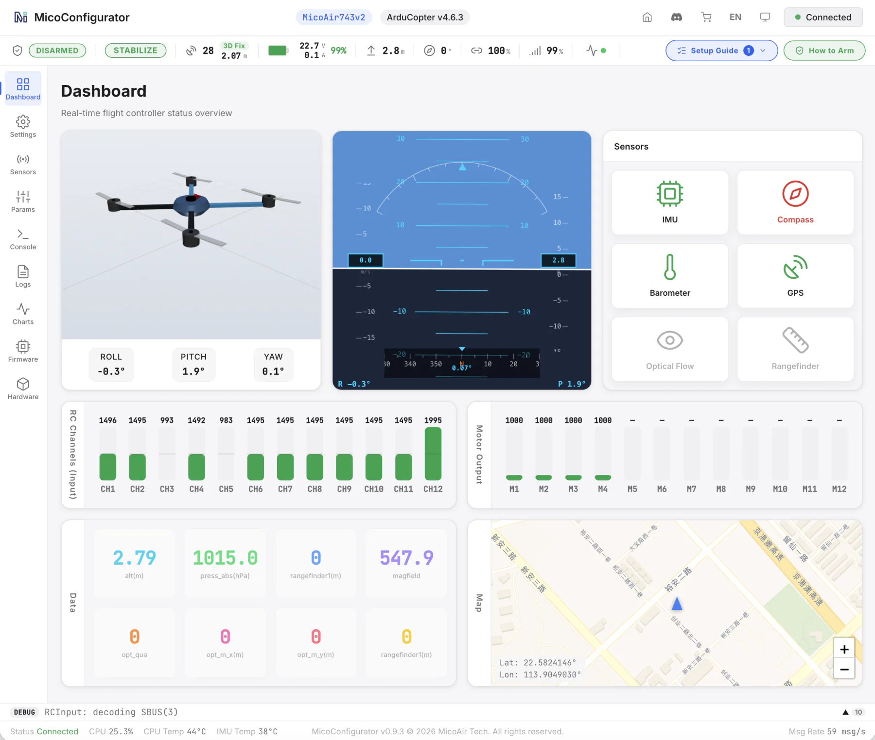
Open MicoConfigurator in Chrome or Edge. After entering DFU mode, select the board and firmware in the browser to flash the flight controller. Windows requires a DFU driver.
ArduPilot
PX4
INAV
Betaflight
Firmware Flashing and Recovery
Updating Firmware
- Back up the current parameters.
- Use MicoConfigurator or Mission Planner to update to stable firmware online.
- After flashing is complete, power-cycle the flight controller.
Entering DFU Mode
- Disconnect the flight controller from its power supply and USB.
- Press and hold the
BOOTbutton. - While holding the button, connect the USB Type-C cable.
- Release the button once the computer detects the DFU device.
- Select the correct firmware target on the firmware/DFU page in MicoConfigurator and flash the firmware.
In DFU mode, the flight controller does not appear as a serial port in Device Manager as it does when normal firmware is running, and the LED indicators do not operate. This is normal.
Appendix A: MCU Pin Assignments
This table is primarily intended for low-level driver development and hardware debugging. It is generally not needed for routine assembly or parameter configuration.
| Category | Device / Function | Bus / Peripheral | Signal | MCU Pin |
|---|---|---|---|---|
| IMU | ICM45686 | SPI3 | MOSI | PC12 |
| IMU | ICM45686 | SPI3 | MISO | PC11 |
| IMU | ICM45686 | SPI3 | SCLK | PC10 |
| IMU | ICM45686 | SPI3 | ICM45686_CS | PA15 |
| IMU | ICM45686 | GPIO | ICM45686_DR | PD2 |
| IMU | BMI088 | SPI2 | MOSI | PC3 |
| IMU | BMI088 | SPI2 | MISO | PC2 |
| IMU | BMI088 | SPI2 | SCLK | PD3 |
| IMU | BMI088 | SPI2 | BMI088_GYRO_CS | PD5 |
| IMU | BMI088 | SPI2 | BMI088_ACCEL_CS | PD4 |
| IMU | BMI088 | GPIO | BMI088_GYRO_DR | PC15 |
| IMU | BMI088 | GPIO | BMI088_ACCEL_DR | PC14 |
| Barometer | SPA06 | I2C2 | SCL | PB10 |
| Barometer | SPA06 | I2C2 | SDA | PB11 |
| Barometer | SPA06 | GPIO | SPL06_DR | PD0 |
| Magnetometer | IST8310 | I2C2 | SCL | PB10 |
| Magnetometer | IST8310 | I2C2 | SDA | PB11 |
| Motor output | PWM | TIM1/CH4 | M1 | PE14 |
| Motor output | PWM | TIM1/CH3 | M2 | PE13 |
| Motor output | PWM | TIM1/CH2 | M3 | PE11 |
| Motor output | PWM | TIM1/CH1 | M4 | PE9 |
| Motor output | PWM | TIM3/CH4 | M5 | PB1 |
| Motor output | PWM | TIM3/CH3 | M6 | PB0 |
| Motor output | PWM | TIM4/CH1 | M7 | PD12 |
| Motor output | PWM | TIM4/CH2 | M8 | PD13 |
| Motor output | PWM | TIM15/CH1 | M9 | PE5 |
| Motor output | PWM | TIM15/CH2 | M10 | PE6 |
| LED strip | PWM | TIM4/CH3 | — | PD14 |
| Buzzer | GPIO | — | — | PD15 |
| VTX power control | GPIO | — | — | PE15 |
| OSD | AT7456E | SPI1 | MOSI | PA7 |
| OSD | AT7456E | SPI1 | MISO | PA6 |
| OSD | AT7456E | SPI1 | SCLK | PA5 |
| OSD | AT7456E | SPI1 | OSD_CS | PB12 |
| External crystal | External | 8 MHz | OSC_IN | PH0 |
| External crystal | External | 8 MHz | OSC_OUT | PH1 |
| Status LED | GPIO_OUTPUT | RED | — | PE3 |
| Status LED | GPIO_OUTPUT | BLUE | — | PE4 |
| Status LED | GPIO_OUTPUT | GREEN | — | PE2 |
| Button | — | BOOT | — | BOOT0 |
| CAN | — | CAN1 | TX | PB9 |
| CAN | — | CAN1 | RX | PB8 |
| I2C | — | I2C1 | SDA | PB7 |
| I2C | — | I2C1 | SCL | PB6 |
| UART | — | UART1 | TX | PA9 |
| UART | — | UART1 | RX | PA10 |
| UART | VTX-HD | UART2 | TX | PA2 |
| UART | VTX-HD | UART2 | RX | PA3 |
| UART | GPS | UART3 | TX | PD8 |
| UART | GPS | UART3 | RX | PD9 |
| UART | — | UART4 | TX | PA0 |
| UART | — | UART4 | RX | PA1 |
| UART | RCIN | UART6 | TX | PC6 |
| UART | RCIN | UART6 | RX | PC7 |
| UART | ESC_Telemetry | UART7 | RX | PE7 |
| UART | Bluetooth Telemetry | UART8 | TX | PE1 |
| UART | Bluetooth Telemetry | UART8 | RX | PE0 |
| USB | — | USB | USB_DM | PA11 |
| USB | — | USB | USB_DP | PA12 |
| SD card | — | SDMMC2 | D0 | PB14 |
| SD card | — | SDMMC2 | D1 | PB15 |
| SD card | — | SDMMC2 | D2 | PB3 |
| SD card | — | SDMMC2 | D3 | PB4 |
| SD card | — | SDMMC2 | CLK | PD6 |
| SD card | — | SDMMC2 | CMD | PD7 |
| Debug interface | — | SWD | SWDIO | PA13 |
| Debug interface | — | SWD | SWCLK | PA14 |
| Battery sensing | Voltage divider ratio 1:21 | ADC | Voltage | PC0 |
| Battery sensing | — | ADC | Current | PC1 |